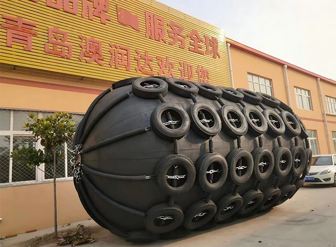
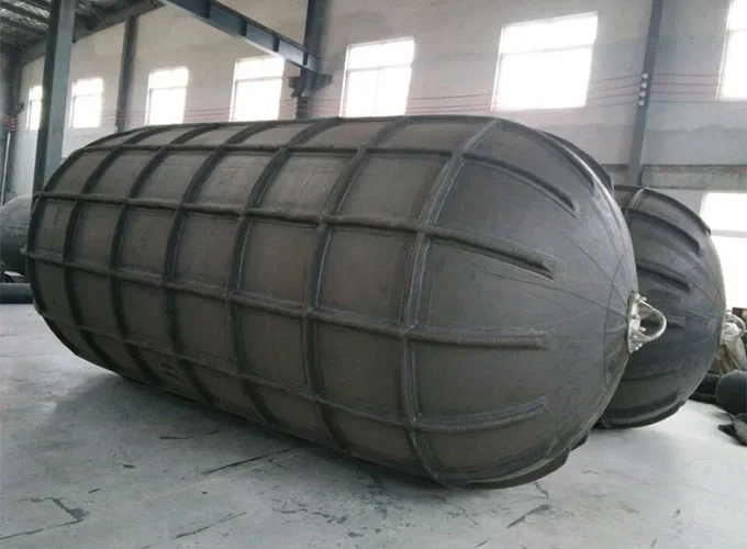
Building airbags are one of the product categories offered by Aorunda. As a direct-sales manufacturer, we can customize products to meet your specific scheduling requirements and provide comprehensive technical support.
What is a Building Airbag?
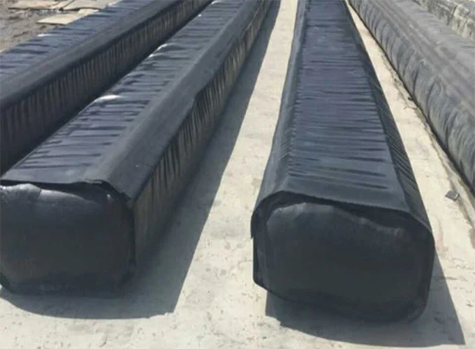
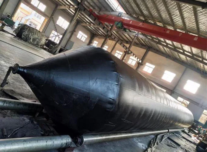
A construction airbag is an inflatable and collapsible cylindrical bag-like component primarily used to create hollow cavities within concrete structures. This product is easy to operate, convenient to use, and highly durable; in its deflated state, the material is soft and pliable, allowing it to be freely folded, coiled, or compressed. Once inflated, however, it possesses sufficient strength to withstand the immense pressure exerted by concrete.
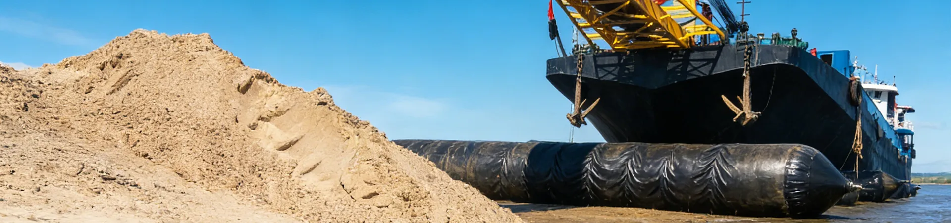
Currently, our products of this type are widely utilized in the construction of reinforced concrete components, spanning applications such as pile foundations, roofs, floor slabs, columns, and beams, as well as various civil engineering and hydraulic projects (e.g., shipyards, slipways, and docks).
Engineering practice has demonstrated that the construction process utilizing inflatable rubber core molds is straightforward. Not only does it effectively conserve materials, but it also offers exceptional flexibility in shaping, allowing for the creation of ducts or channels in a wide variety of forms—including circular, elliptical, rectangular, arched, and trapezoidal—to suit specific project requirements.
Furthermore, these airbags can be employed to create linear voids and similar structural features, thereby facilitating the realization of lightweight and thin-walled hollow designs in architectural structures. This capability effectively breaks through the limitations of traditional concrete construction, which previously relied exclusively on rigid formwork.
Performance Features
1. Scientific and Rational Design
Our products utilize inflatable rubber core molds or casting components, ensuring that the finished products fully comply with design specifications. The operation is simple, saving labor, time, and materials.
2. Excellent Aging Resistance and Long Service Life
This product is manufactured through a vulcanization process involving synthetic rubber, natural rubber, and reinforcing layers. It exhibits exceptional resistance to expansion, as well as excellent flexibility and elasticity, enabling it to meet operational demands across a wide range of working conditions.
3. Wide Operating Temperature Range
The material properties remain stable and undergo no changes within a temperature range of -10°C to +90°C.
4. Facilitates Lightweight Construction
These air bladders are particularly well-suited for the fabrication of prestressed hollow concrete components. Thanks to the use of rubber core molds, the self-weight of the components is reduced by approximately 20% compared to solid prestressed components.
This not only reduces the structural load on the building's superstructure but also allows for shorter pile foundations and increased spans, making the construction process simpler and safer.
5. Simple, Safe, and Eco-Friendly Construction Process
Using this product requires only a few simple tools and involves no complex or specialized procedures. One simply needs to insert the core mold into the steel reinforcement cage, inflate it to the required working pressure, and then pour the concrete.
Once the concrete has set, the air is released from the core mold to complete the component's formation; the entire process generates absolutely no environmental pollution.
Parameter Standards
|
Item
|
Parameters
|
|
Thickness Tolerance (mm)
|
2.5
|
|
Appearance
|
Surface: Smooth, free of exposed fabric
|
|
Adhesion Strength (N/25mm)
|
≥12
|
|
Applicable Temperature (°C)
|
-10 to 80
|
Product Specifications
|
Common Specifications
|
Non-standard specifications; double-tube with outer jacket
|
|
¢180mm X 6-20m
|
¢400mm X 10-40m
|
350 X 530(540)mm X 10-40m
|
|
¢200(¢220)mm X 10-20m
|
¢500mm X 10-40m
|
320 X 520(540) X 10-40m
|
|
¢240(¢250)mm X 15-40m
|
¢600mm X 10-40m
|
350(360) X 560mm X 10-40m
|
|
¢300(¢330)mm X 15-40m
|
¢620mm X 10-40m
|
360 X 640(650)mm X 10-40m
|
|
¢350(¢360)mm X 10-40m
|
¢700mm X 10-40m
|
320 X 520(550)mm X 10-40m
|
|
Other sizes are available for customization.
|
Operational Guidelines
1. Place the construction airbag (core mold) into the formwork, pull the core mold into the steel reinforcement cage, and ensure that its longitudinal seam is facing upwards.
2. Inflating the Core Mold
(1) Open the valve and inflate the core mold until the specified pressure value is reached, then close the valve.
(2) Working Pressure (refer to the attached table).
3. Securing and Positioning
(1) Since the inflated core mold tends to float upwards during concrete vibration, it must be secured both vertically (top and bottom) and horizontally; additionally, weighting measures should be applied to counteract the buoyant force.
(2) For a core mold with a diameter of φ250mm, the standard spacing for stirrups (transverse reinforcement) is 80cm. If the core mold diameter increases, the stirrup spacing should be reduced accordingly.
4. Concrete Pouring
(1) The concrete pouring process is fundamentally the same as that used for pouring solid structural members.
(2) High-frequency internal vibrators should be applied simultaneously from both sides to prevent displacement of the core mold.
(3) The tip of the vibrator must strictly avoid contact with the body of the core mold to prevent damage that could lead to air leakage.
5. Once the concrete structural member has set, the core mold can be deflated and withdrawn from the formwork.
6. Clean the core mold, then perform an airtightness test and a visual inspection.
How to Store and Maintain Building Airbags?
1. After use, the core mold must be thoroughly cleaned with clean water. If the core mold is not to be used immediately, store it in a well-ventilated, dry environment, and keep it away from contact with oils, acids, or alkaline substances.
2. During use at the construction site, strictly avoid allowing the core mold to come into contact with sharp or hard objects.
3. Each time the inflated core mold is withdrawn from the formwork, use a brush (a nylon brush is recommended) and running water to clean it, removing any residual concrete from the surface to keep the core mold clean. 4. If the core mold develops an air leak or the sealing film detaches, use a grinding wheel to abrade the area requiring repair; subsequently, apply adhesive and affix a new piece of sealing film to complete the repair. If the fiber layer is damaged, it should be repaired by wrapping it with tape.
Working Press
|
Diameter(mm)
|
Working press (MPa)
|
|
80
|
0.12
|
|
120
|
0.10
|
|
150
|
0.08
|
|
200
|
0.07
|
|
250
|
0.05
|
|
400
|
0.04
|
|
500
|
0.035
|
|
600
|
0.03
|
|
700
|
0.027
|
|
800
|
0.026
|
|
900
|
0.025
|
|
2200
|
0.005
|